KISSLora Sensors
Steps to get it going:
- Install Arduino IDE
- Install SparkFun AVR drivers
- Install The Things Network and SoftPWM libraries
- Define device on TTN Console
- Get Id’s
Some handy links:
- Github repository with all kinds of information.
- The schematic of the thingy.
- TheThingsNetwork user forum.
- Help to build the community.
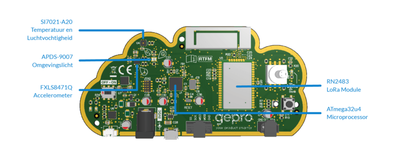
On board you will find:
- U5: Microchip RN2483 Low-Power Long Range LoRa™ Technology Transceiver Module.
- U1: ATmega32u4 8-bit Microcontroller with 32K bytes of ISP Flash and USB Controller.
- U2: FXLS8471Q 3-Axis Linear Accelerometer.
- U3: APDS-9007 Ambient Light Photo Sensor with Logarithmic Current Output.
- U4: SI7021-A20 I2C Humidity and Temperature sensor.
There are 7 connectors on the board.
- J1: JTAG connector, which can be used to program and debug the controller.
- J2: I2C connector. With the cable you have received a connector (J7, 3-pins term block plug) which fits in there.
- J3: SPI connector.
- J4: Power jack, which accepts 5 volts. I will try to find out what the minimum and maximum rating is. It draws less than 150 mA.
- J5: Battery connector. Vmax: 4.25V Vnom: 3.7V Low Batt @ ≤3.1 V C 350 mAh I_charge: 100mA
- J6: MicroUSB connector, also for power and for communication with your laptop.
- J8: LoRa programming header, which only has holes, no pins connected (yet).
The board has a couple of LEDs. The red LED (D6) is lighting up when the battery is charging. When there is no battery connected it stays off. The green LED (D5) is only on when the board is powered (Power Good) via J4 and/or J5 AND the power switch is on. There is also a blue LED (D2) and an RGB LED (D3) on the board. The RGB is user programmable.
Resources:
https://www.arduino.cc/en/main/software
https://github.com/YourproductSmarter/KISSLoRa-demo
https://diystuff.nl/lorawan/kisslora/