Using LSC Smart Connect's Power Plug with ESPHome

In this post I describe the steps needed to prepare a LSC Smart Connect power plug -sold by Action- for use with Home Assistant/ESPHome. I simply gathered instructions I found on the web.
You need to be able to solder thin copper wires on the Smart Plug’s circuit board. All steps are at your own risk!
- Open the plug by undoing the two small screws at the bottom. There are two internal plastic clips on the opposite side. You now see the small ESP board standing upright, this is the TYWE3L module, see it’s datasheet below under resources. The connections are as follows:
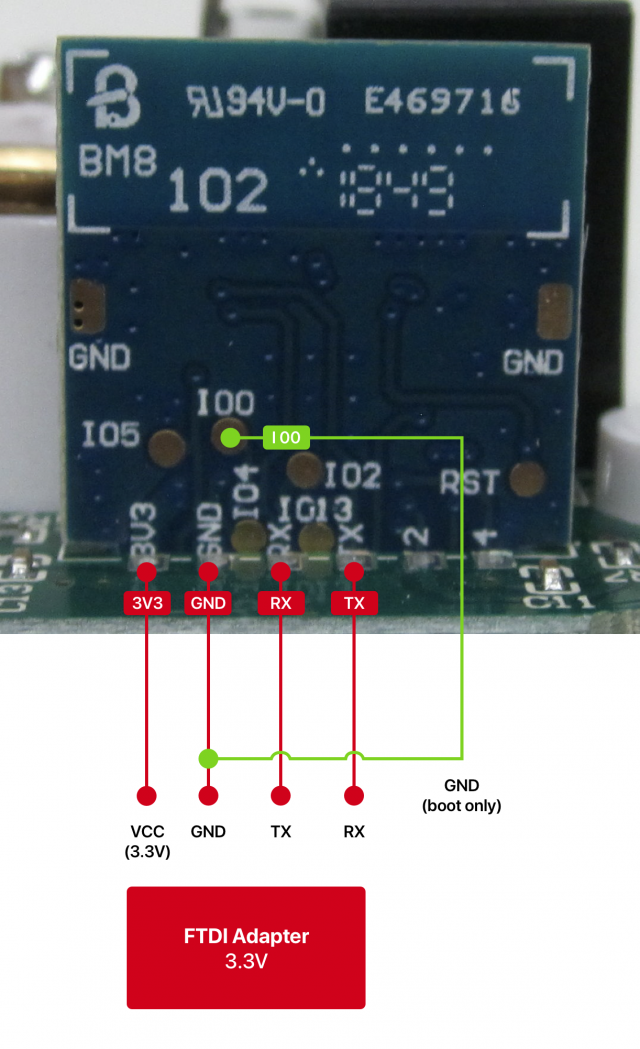
So TX en RX are the two middle ones from the six connections on the board. 3v3 is at bottom left, make sure that your FTDI module is set to 3v3 VCC because this plug get its power from the FDTI, powered by mains would be to dangerous. (The Action LED strip with 12V can be flashed using it’s own power)
Module <-> FTDI-dapter
3V3 <-> VCC
GND <-> GND
RX <-> TX
TX <-> RX
I00 <-> GND (only during boot)
Create a new device config inside your ESPhome installation with this configuration and compile the binary.
esphome:
  name: <YOURPLUGNAME>
  platform: ESP8266
  board: esp01_1m

wifi:
  ssid: "<WIFISSID>"
  password: "<WIFIPASSWORD>"

# Enable logging
logger:

# Enable Home Assistant API
api:
  password: "<YOURPASSWORD>"

ota:
  password: "<YOURPASSWORD>"

switch:
  - platform: gpio
    pin: 12
    name: "ESP switch"
    id: relay
    on_turn_on:
      - switch.turn_on: blue_led
    on_turn_off:
      - switch.turn_off: blue_led

  - platform: gpio
    pin:
      number: GPIO04
      inverted: yes
    id: blue_led
    internal: yes

binary_sensor:
  - platform: gpio
    pin:
      number: GPIO14
      inverted: True
    name: "ESP Switch Button"
    on_press:
      then:
        - switch.toggle: relay
    internal: yes
    ```